


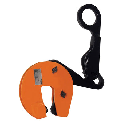
Caldwell Model ASTL Structural Shape Lifting Clamp Non-Locking Type
Caldwell Model ASTL Structural Shape Lifting Clamp Non-Locking Type is backordered and will ship as soon as it is back in stock.
Safe & Secure Payments

-
Caldwell
Caldwell Model CPP Pipe Pick Concrete Pipe Lifter
Regular price$998.00 – $1,456.00Unit price -
-
Sale
Caldwell
Caldwell Model 32 Adjustable Spreader Beam for Overhead Lifting
Sale price$1,771.00 – $5,310.00Save up to $380.71Unit price -
-
Sale
Caldwell
Caldwell Drum Lifter Locking Type Clamp
Sale price $1,595.00 Was: Regular price $1,754.50 Save $159.50Unit price -
-
Sale
Caldwell
Caldwell DURA-MOD DM30-4 Modular 4-Point Spreader Beam
Sale price$693.00 – $1,121.00Save up to $486.42Unit price -
-
Sale
Caldwell
Caldwell Model 80H Dixon Coil Hook with Pivoting Wedge
Sale price$1,078.00 – $3,320.00Save up to $237.14Unit price -
-
Sale
Caldwell
Adjustable Spreader / Lifting Beam
Sale price$931.00 – $4,668.00Save up to $333.43Unit price -
-
Sale
Caldwell
CPL Leveling Pipe Lifter for Concrete Pipe Positioning
Sale price$4,878.00 – $10,936.00Save up to $524.00Unit price -
-
Sale
Caldwell
Model PLB Precision Lifting Boom
Sale price$20,032.00 – $21,080.00Save up to $2,108.00Unit price -
-
Sale
Caldwell
Model FDD Fork Lift Drum Lifter & Dumper
Sale price $1,269.00 Was: Regular price $1,369.00 Save $100.00Unit price -
-
Sale
Caldwell
Caldwell Wall Pick Lifting Clamp
Sale price$2,768.00 – $3,192.00Save up to $319.20Unit price -
-
Sale
Caldwell
Caldwell Model 176 Adjustable Concrete Pressure Tong with Urethane Pads
Sale price$1,892.00 – $2,596.00Save up to $259.60Unit price -
-
-
-
Sale
Caldwell
Caldwell Model M Locking Type Structural Shape Lifting Clamp
Sale price$698.00 – $1,472.00Save up to $147.20Unit price -
-
Sale
Caldwell
Caldwell Model ASTL Structural Shape Lifting Clamp Non-Locking Type
Sale price $1,299.00 Was: Regular price $1,428.90 Save $129.90Unit price -
-
Sale
Caldwell
Caldwell Model AST Non-Locking Structural Shape Lifting Clamp
Sale price $919.00 Was: Regular price $1,010.90 Save $91.90Unit price -
-
Sale
Caldwell
Caldwell Model SCPA Locking Screw Type Vertical & Side Pull Lifting Clamp
Sale price$1,082.00 – $2,266.00Save up to $226.60Unit price -
-
Sale
Caldwell
Caldwell Model LPA Vertical 180° Side Pull Lifting Clamp
Sale price$152.67 – $1,806.00Save up to $180.60Unit price -
-
Sale
Caldwell
Caldwell Model JPA Vertical 180° Side Pull Lifting Clamp
Sale price$1,535.00 – $2,530.00Save up to $253.00Unit price -
-
Sale
Caldwell
Caldwell Model TLA Vertical Locking Lifting Clamp 180° Arc
Sale price $1,170.00 Was: Regular price $1,287.00 Save $117.00Unit price -
-
-
-
Sale
Caldwell
Caldwell Model RSC Locking Type Vertical Lifting Screw Clamp
Sale price $1,610.00 Was: Regular price $1,771.00 Save $161.00Unit price -
-
Sale
Caldwell
Caldwell Model SCP Vertical & Horizontal Locking Screw Type Plate Clamp
Sale price $1,574.00 Was: Regular price $1,731.40 Save $157.40Unit price -
-
Sale
Caldwell
Caldwell Model PCK-SL Locking Screw Type Vertical Lifting Clamp
Sale price $5,422.00 Was: Regular price $5,964.20 Save $542.20Unit price -
-
Sale
Caldwell
Caldwell Model LA Vertical 180° Ergonomic Lifting Clamp
Sale price $846.00 Was: Regular price $930.60 Save $84.60Unit price -
-
Sale
Caldwell
Caldwell Model LP Vertical Locking Lifting Clamp
Sale price $1,427.00 Was: Regular price $1,569.70 Save $142.70Unit price -
-
Sale
Caldwell
Caldwell Model JP Vertical 90° Side Pull Locking Lifting Clamp
Sale price $1,759.00 Was: Regular price $1,934.90 Save $175.90Unit price -
-
Sale
Caldwell
Caldwell Model TL Vertical 90° Locking Lifting Clamp
Sale price$772.00 – $895.00Save up to $89.50Unit price -
-
Sale
Caldwell
Caldwell Model LJ Vertical Lifting Clamp Locking Type
Sale price $1,266.00 Was: Regular price $1,392.60 Save $126.60Unit price -
-
Sale
Caldwell
Caldwell Model L Vertical Locking Lifting Clamp
Sale price$963.00 – $1,255.00Save up to $125.50Unit price -
-
Sale
Caldwell
Caldwell Model J Vertical Lifting Clamp – Locking Type
Sale price $1,043.00 Was: Regular price $1,147.30 Save $104.30Unit price -
-
Sale
Caldwell
Caldwell Model FR Vertical Locking Plate Lifting Clamp
Sale price$1,023.00 – $1,117.00Save up to $111.70Unit price -
-
Sale
Caldwell
Caldwell Model BD Non-Locking Plate Lifting Clamp
Sale price$597.00 – $745.00Save up to $74.50Unit price -
-
Sale
Caldwell
Caldwell Beam Clamp Locking Type
Sale price$741.00 – $1,125.00Save up to $112.50Unit price -
-
Sale
Caldwell
Caldwell Model LHC Horizontal Lifting Clamp
Sale price$412.00 – $818.00Save up to $81.80Unit price -
-
Sale
Caldwell
Caldwell Model DWS Locking Lifting Clamp
Sale price$838.00 – $1,273.00Save up to $127.30Unit price -
-
-
-
-
-
Sale
Caldwell
Caldwell Model DLT DLT-1-20, Die Lifting Tong
Sale price $1,937.00 Was: Regular price $2,130.70 Save $193.70Unit price -
-
Sale
Caldwell
Caldwell Model 77 Bale Lifting Tongs
Sale price $11,178.00 Was: Regular price $13,150.58 Save $1,972.58Unit price -
-
Sale
Caldwell
Caldwell EB-15 Fixed Length Fork Lift Boom
Sale price$1,560.00 – $2,320.00Save up to $232.00Unit price -
-
-
-
-
-
Sale
Caldwell
Caldwell Model GC Girder Clamp — 15–25 Ton
Sale price$4,425.00 – $6,773.00Save up to $677.30Unit price -
-
Sale
Caldwell
Caldwell Model F Beam Grab Construction Lifter
Sale price$2,509.00 – $9,752.00Save up to $975.20Unit price -
-
Sale
Caldwell
Caldwell Model BWC Beam Web Clamp — 67-1404
Sale price$4,094.00 – $4,338.00Save up to $409.40Unit price -
-
Sale
Caldwell
Caldwell Model BC Beam Clamp 1-Ton Capacity
Sale price $478.00 Was: Regular price $512.14 Save $34.14Unit price -
-
Sale
Caldwell
Caldwell BFC Beam Flange Clamp 1–11 Ton
Sale price$428.00 – $747.69Save up to $74.77Unit price -
-
Sale
-
-
Sale
Caldwell
Caldwell Model RLT Rail Tongs — 1 & 2 Ton
Sale price$1,112.00 – $1,480.00Save up to $148.00Unit price -
-
Sale
-


Product Description
Structural Shape Lifting Clamp Non-Locking Type — Remote-Release Design for Turning, Lifting & Stacking Beams
The Renfroe Model ASTL Structural Shapes Lifting Clamp (Non-Locking Type) is a 1.5-ton capacity clamp engineered for lifting, turning, and stacking lightweight beams and structural shapes in steel fabrication and construction environments. It is designed for use with a constant tension applied to the lifting shackle throughout the lift, and its horizontal shackle orientation allows beams to be lifted with the web in a near-horizontal position by positioning the clamp with the shackle over the web and between the flanges. When a beam is lying horizontal and the clamp is placed with the shackle overhanging the flange, the load can be lifted, rotated 90 degrees, and raised into a vertical position. This clamp is suited for contractors, ironworkers, riggers, and steel erectors who regularly handle structural sections and require controlled, repeatable lifts.
What distinguishes the Model ASTL from the base Model AST is the addition of a built-in linkage mechanism that allows the clamp to be removed remotely — without requiring personnel to manually release it at the load. By setting the load down with the sling slack and then lifting the crane hook, the clamp disengages, keeping workers out of the lift zone during release. This remote-removal capability is a meaningful operational safety advantage over clamps that require hands-on release at the point of load.
Key Features & Benefits
Remote Removal via Linkage Mechanism
The ASTL's integrated linkage allows the clamp to be released remotely by setting the load down with sling slack, then lifting the crane hook. This eliminates the need for a worker to approach the suspended or freshly set load to release the clamp, reducing exposure to hazard at the point of lift. For contractors working in steel erection or beam staging, this feature directly supports safer rigging workflows.
Horizontal Shackle for Web and Flange Lifts
The horizontal shackle orientation enables the clamp to be positioned over the web and between the flanges of a beam, allowing near-horizontal lifts of structural shapes with improved load control. This configuration is not incidental — it is the core design intent of both the AST and ASTL models, and it gives riggers the geometry needed to handle I-beams, channels, and similar profiles predictably.
90-Degree Turn Capability
With the clamp placed so the shackle overhangs the flange of a horizontally lying beam, the load can be lifted, turned 90 degrees, and raised to a vertical position in a single rigging setup. This turn-and-lift capability is particularly valuable in beam staging, stacking operations, and structural erection where orientation changes are routine.
Designed for Constant-Tension Operation
The clamp is engineered to operate with constant tension on the lifting shackle during the lift. This is a defined operating condition — not a recommendation — and contractors should plan rigging accordingly to ensure the clamp functions within its intended parameters throughout the lift cycle.
Non-Locking Clamp Type
The ASTL is a non-locking clamp, which is matched to specific structural shape lifting tasks where the load geometry and constant shackle tension provide the gripping action. Understanding the clamp type is essential for selecting the correct tool for the application and for complying with proper rigging practices.
Common Applications
Lifting Lightweight Beams and Structural Shapes
The primary use case for the Model ASTL is lifting lightweight beams and structural shapes — I-beams, channels, angles, and similar profiles — in fabrication shops, staging yards, and active construction sites.
Turning Beams from Horizontal to Vertical
With the shackle overhanging the flange of a beam lying flat, the ASTL allows the beam to be lifted, rotated 90 degrees, and raised to a vertical orientation, a common requirement in structural steel erection and pre-fabrication workflows.
Stacking Structural Shapes
The clamp is designed for stacking lightweight structural shapes, supporting organized material handling in steel yards and fabrication facilities where beams must be sorted, layered, or staged by size and orientation.
Remote-Release Lifting Operations
In applications where minimizing personnel exposure near the load during clamp release is a priority — such as elevated placements or congested erection areas — the ASTL's remote-removal linkage allows the crane operator to release the clamp without a worker physically accessing the load.
Compatible Materials
- Lightweight steel I-beams (web and flange lifting)
- Steel channels
- Steel angles
- Other structural steel shapes with flanged or webbed profiles
- Plate stock up to 0.75 in. maximum thickness
Product Documents
- Download Catalog
- Download Manual
- Lifting Clamp Survey Report
- Lifting Tool Inventory and Maintenance Form
- Minimum Recommended Clamp Inspections
- Renfroe Repair Kits Catalog
Application Instructions
Horizontal Web Lift Setup
- Read and understand the Operator's Manual (OM 211-AST/L) before placing the clamp into service.
- Inspect the clamp before each lift per the inspection instructions in the Operator's Manual.
- Position the clamp on the beam with the shackle placed over the web and between the flanges.
- Connect rigging to the lifting shackle using a flexible connection between the crane and the clamp shackle — do not attach the clamp directly to the crane hook.
- Apply constant tension to the lifting shackle before and throughout the lift.
- Do not lift over workmen or safety areas during the lift.
90-Degree Turn Lift Setup
- With the beam lying in a horizontal position, place the clamp with the shackle overhanging the flange.
- Connect rigging using a flexible connection to the crane hook.
- Apply constant tension to the shackle and lift the beam.
- Rotate the beam 90 degrees and raise it to the vertical position as required.
- Ensure the load does not exceed the rated capacity of the clamp at any point during the turning operation.
Remote Clamp Removal
- Set the load down at the target location.
- Allow the sling to go slack.
- Lift the crane hook — the linkage mechanism will disengage the clamp remotely without requiring manual release at the load.
Technical Specifications
| Specification | Details |
|---|---|
| Model Number | ASTL-01.50-A |
| Capacity | 1.5 tons |
| Clamp Type | Non-Locking |
| Weight | 24 lbs. |
| Clamp Height | 8.5 in. |
| Clamp Length | 7 in. |
| Clamp to Cam Length | 3 in. |
| Clamp Width | 2.56 in. |
| Overall Clamp Length | 13 in. |
| Pivot Length | 2.5 in. |
| Max Plate Thickness | 0.75 in. |
| Shackle Thickness | 0.62 in. |
| Remote Removal | Yes — via linkage mechanism |
Safety Data Summary
Safe Handling
- Read and understand the Operator's Manual before placing the clamp in service; bring to your immediate supervisor before first use.
- Constant tension must be applied to the lifting shackle at all times when lifting loads.
- Do not attach the clamp directly to the crane hook; always use a flexible connection between the crane and the clamp shackle.
- Do not use a heavy flexible connection.
- Do not lift over workmen, safety areas, or personnel.
- Use clamps within their rated capacity; do not overload.
- Do not use a clamp that has been overloaded.
- Do not side load with this clamp.
- Use an adequate number of clamps to balance the load; do not lift unbalanced loads.
- Use correct clamp for the job; do not use a large-capacity clamp to lift light loads.
- Do not alter, grind, weld, or modify the clamp in any manner.
- Do not rush; do not improvise.
- Inspect the clamp before each lift and follow inspection and maintenance instructions in the Operator's Manual.
- Use only Renfroe replacement parts to ensure proper clamp operation.
- Consult the Operator's Manual or Renfroe when in doubt about application or operation.
Frequently Asked Questions
Q: What is the difference between the Model AST and the Model ASTL?
A: Both models are designed for lifting, turning, and stacking lightweight beams and structural shapes with constant tension on the shackle. The Model ASTL adds a linkage mechanism that allows the clamp to be removed remotely — by setting the load down with the sling slack and then lifting the crane hook — without requiring a worker to manually release the clamp at the load.
Q: How does the horizontal shackle design improve load control when lifting beams?
A: The horizontal shackle allows the clamp to be positioned with the shackle over the web and between the flanges of the beam. This placement improves load control by centering the lift point relative to the beam's cross-section when lifting with the web in a near-horizontal position.
Q: Can this clamp be used to turn a beam from horizontal to vertical?
A: Yes. By placing the clamp with the shackle overhanging the flange of a horizontally lying beam, the beam can be lifted, turned 90 degrees, and raised to a vertical position in a single rigging setup.
Q: What is the maximum plate thickness this clamp can accommodate?
A: The ASTL-01.50-A accepts plate and flange thicknesses from 0 to 0.75 in. maximum.
Q: Is constant tension on the shackle required during the lift?
A: Yes. The Model ASTL is designed to operate with constant tension applied to the lifting shackle. This is a defined operating condition for both the AST and ASTL models and must be maintained throughout the lift.
Q: Can the clamp be attached directly to the crane hook?
A: No. The Operator's Manual explicitly states that the clamp must not be attached directly to the crane hook. A flexible connection must be used between the crane and the clamp shackle, and that connection should not be heavy.
-
Sale
Husqvarna
Husqvarna Hepa Dust Extractor - 130 H
Sale price $6,253.20 Was: Regular price $6,948.00 Save $694.80Unit price -
-
Sale
Husqvarna
Husqvarna K 540i Power Cutting Saw
Sale price $944.10 Was: Regular price $1,049.00 Save $104.90Unit price -
-
Sale
-
-
Sale
Husqvarna
Sale price $2,444.40 Was: Regular price $2,716.00 Save $271.60Unit price -
-
Sale
-
-
 Sale
SaleHusqvarna
Sale price $1,614.60 Was: Regular price $1,794.00 Save $179.40Unit price -
 Sale
SaleHusqvarna
Sale price$118,153.29 – $122,841.00Save up to $13,649.00Unit price -
Sale
Husqvarna
Sale price $5,635.80 Was: Regular price $6,262.00 Save $626.20Unit price -


